First, let’s start with prerequisites. You should be familiar with vxlan, leaf-spine, evpn, cumulus switches. If you are not or you want to refresh your memory you can check the links below:
What is a VXLAN?
You can find a lot of info on this over the internet, but here are 2 articles:
https://www.sdxcentral.com/networking/virtualization/definitions/what-is-vxlan/
https://medium.com/@NTTICT/vxlan-explained-930cc825a51
What is evpn?
Here is a good answer: https://rickmur.com/evpn-rfc-7432-explained/
What is Cumulus?
Cumulus Linux is an open source Linux-based networking operating system for bare metal switches. Cumulus Networks is the software company that has designed it.
More info, here:
https://en.wikipedia.org/wiki/Cumulus_Networks
https://cumulusnetworks.com/about/
Leaf-Spine arhitecture:
https://blog.westmonroepartners.com/a-beginners-guide-to-understanding-the-leaf-spine-network-topology/
https://blog.mellanox.com/2018/04/why-leaf-spine-networks-taking-off/
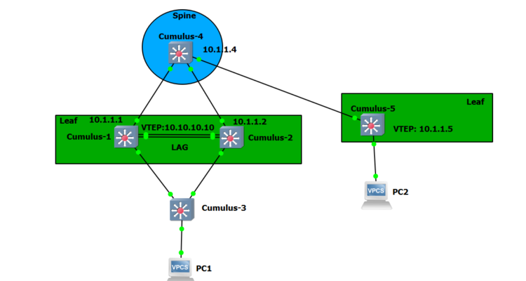
I’ve used GNS3 as a lab environment. Also, I’ve tried to make the topology as simple as possible so it won’t take too many resources from the host.
I’ve created 2 leaves and one spine. If you have enough resources you can expand the topology to have more spines and leaves. The Cumulus OS version I’ve used is 3.7.10.
The Cumulus documentation i’ve used is this:
https://docs.cumulusnetworks.com/version/cumulus-linux-37/Network-Virtualization/
I’ve configured a VXLAN between the 2 leaves. Leaf 1 is made of Cumulus switch1 and 2, which are configured with a LAG towards cumulus 3 switch, and also an anycast IP so they act as one VTEP ( https://docs.cumulusnetworks.com/version/cumulus-linux-37/Network-Virtualization/VXLAN-Active-Active-Mode/ ). Also, Cumulus 1 and 2 switches are configured with VRR (Virtual Router Redundancy). VRR is similar to VRRP or HSRP. Cumulus 3 switch role is only so I could configure a LAG.
Leaf 2 has only one Cumulus switch. It should have been similar to the other leaf but to keep the topology as light as possible I’ve used just one switch, which is enough to configure BGP,evpn,vxlan.
There is only 1 VLAN and 1 vxlan(id 100 for both) in the lab, but that’s enough as an example.
EVPN is used as a control-plane mechanism to learn and share the MAC addresses. EVPN is often referred to as the means of implementing controllerless VXLAN.
Important: we need an anycast IP attached to the loopback on each clag pair, which is for northbound traffic, and an anycast IP for each clag pair for vrr, which is for southbound traffic.
So let’s start with the creation of VLANs, LAG, and VRR:
net commands
============

switch1# net add clag peer sys-mac 44:38:39:FF:01:01 interface swp5-6 primary backup-ip 10.0.0.2
switch1# net add vlan 100-200
switch1# net add clag port bond bond1 interface swp1 clag-id 1
switch1# net add bond bond1 bridge trunk vlans 100,200

switch1# net add vlan 100 ip address 192.168.1.252/24
switch1# net add vlan 100 ip address-virtual 00:00:5e:00:01:00 192.168.1.254/24


switch1# net pending
switch1# net commit

switch2# net add clag peer sys-mac 44:38:39:FF:01:01 interface swp5-6 secondary backup-ip 10.0.0.1                                                                                                                                                                                                                                                                 backup-ip 10.0.0.1
switch2# net add vlan 100-200
switch2# net add clag port bond bond1 interface swp1 clag-id 1
switch2# net add bond bond1 bridge trunk vlans 100,200

switch2# net add vlan 100 ip address 192.168.1.253/24
switch2# net add vlan 100 ip address-virtual 00:00:5e:00:01:00 192.168.1.254/24


switch2# net pending
switch2# net commit


switch3# net add bridge bridge ports swp5-6
switch3# net add bridge bridge vids 100,200
switch3# net add bridge bridge pvid 1
switch3# net add interface swp5-6 bridge access 100


switch3# net add bond bond1 bond slaves swp1-2
switch3# net add bond bond1 bridge trunk vlans 100,200
switch3# net pending
switch3# net commit


switch5# net add bridge bridge ports swp5-6
switch5# net add bridge bridge vids 100,200
switch5# net add bridge bridge pvid 1
switch5# net add interface swp5-6 bridge access 100
switch5# net add vlan 100 ip address 192.168.1.251/24

Verification
============
switch1# net show interface
switch1# net show clag
clagctl -v
Next, is the BGP, evpn part. I’ve started with configuring the loopback interfaces and their anycast IPs (anycast only for switches 1 and 2).
Then I moved to BGP and evpn and advertising the loopback IP.
You will notice that there are no neighbor statements. This is because Cumulus can use a feature called BGP unnumbered. This is using the ipv6 link-local addresses to establish the neighbor relationship.
More on this, here: https://cumulusnetworks.com/blog/bgp-unnumbered-overview/
############# BGP routing ##################

/etc/frr/daemons

sudo systemctl enable frr.service
sudo systemctl start frr.service

### EVPN Configuration

switch1# net add loopback lo ip address 10.1.1.1/32
switch1# net add loopback lo clag vxlan-anycast-ip 10.10.10.10

switch1# net add bgp autonomous-system 65001
switch1# net add bgp neighbor swp3 interface remote-as external
switch1# net add bgp l2vpn evpn neighbor swp3 activate
switch1# net add bgp l2vpn evpn advertise-all-vni
switch1# net add bgp network 10.1.1.1/32
switch1# net add bgp network 10.10.10.10/32
switch1# net pending
switch1# net commit


switch2# net add loopback lo ip address 10.1.1.2/32
switch2# net add loopback lo clag vxlan-anycast-ip 10.10.10.10

switch2# net add bgp autonomous-system 65002
switch2# net add bgp neighbor swp3 interface remote-as external
switch2# net add bgp l2vpn evpn neighbor swp3 activate
switch2# net add bgp l2vpn evpn advertise-all-vni
switch2# net add bgp network 10.1.1.2/32
switch2# net add bgp network 10.10.10.10/32
switch2# net pending
switch2# net commit

switch4# net add loopback lo ip address 10.1.1.4/32

switch4# net add bgp autonomous-system 65004
switch4# net add bgp neighbor swp1-2 interface remote-as external
switch4# net add bgp l2vpn evpn neighbor swp1-2 activate
switch4# net add bgp network 10.1.1.4/32
switch4# net pending
switch4# net commit

switch5# net add loopback lo ip address 10.1.1.5/32

switch5# net add bgp autonomous-system 65005
switch5# net add bgp neighbor swp1 interface remote-as external
switch5# net add bgp l2vpn evpn neighbor swp1 activate
switch5# net add bgp l2vpn evpn advertise-all-vni
switch5# net add bgp network 10.1.1.5/32
switch5# net pending
switch5# net commit

Verification
============
net show route
net show route ipv4
Next is the VXLAN part. There is only 1 vlan and 1 vlxan, id 100. This will provide connections between PC1 to PC2 . The VTEP’s will be: switch 1 and 2 , which will act as a single VTEP using the anycast ip of 10.10.10.10, and another VTEP on switch 5.
#### VxLAN Configuration

switch1# net add vxlan vni100 bridge access 100
switch1# net add vxlan vni100 vxlan id 100
switch1# net add vxlan vni100 bridge learning off
switch1# net add vxlan vni100 stp bpduguard
switch1# net add vxlan vni100 stp portbpdufilter
switch1# net add vxlan vni100 vxlan local-tunnelip 10.1.1.1
switch1# net add vxlan vni100 bridge arp-nd-suppress on


switch2# net add vxlan vni100 bridge access 100
switch2# net add vxlan vni100 vxlan id 100
switch2# net add vxlan vni100 bridge learning off
switch2# net add vxlan vni100 stp bpduguard
switch2# net add vxlan vni100 stp portbpdufilter
switch2# net add vxlan vni100 vxlan local-tunnelip 10.1.1.2
switch2# net add vxlan vni100 bridge arp-nd-suppress on

switch5# net add vxlan vni100 bridge access 100
switch5# net add vxlan vni100 vxlan id 100
switch5# net add vxlan vni100 bridge learning off
switch5# net add vxlan vni100 stp bpduguard
switch5# net add vxlan vni100 stp portbpdufilter
switch5# net add vxlan vni100 vxlan local-tunnelip 10.1.1.5
switch5# net add vxlan vni100 bridge arp-nd-suppress on


Verification
============
net show route ipv4
net show evpn vni
net show bgp l2vpn evpn vni 100
net show bgp l2vpn evpn route
net show evpn mac vni 100
The GNS3 project files and the config of the switches can be found in the link below:
https://github.com/czirakim/VxLAN-s-on-Cumulus
Great job, chap!
Thanks, mate!